
Description
The Dynaplaque 2 reference material, qualified mlpc®, meets all the criteria of standard NF P94 117-2 and is used for the following applications:
measurement of the deformability of earthwork platforms and subgrades
determination of their homogeneity during construction.
assessment of the bearing capacity and fatigue behaviour of structures such as car parks, building site tracks, forestry or agricultural roads.
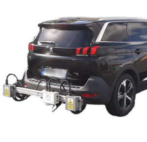
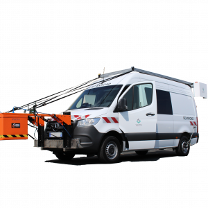
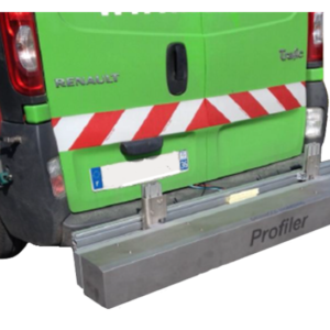
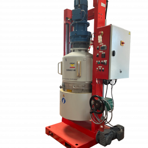
The dynamic stress applied to the platform to be tested is similar in intensity and frequency to that caused by the passage of an axle loaded to 13 tonnes and travelling at 60 km/h. It is generated by the fall of a mass on a damping spring placed on a load plate.
The complex analysis of the impact allows the dynamic deformation modulus of the structure at the test point to be calculated directly.
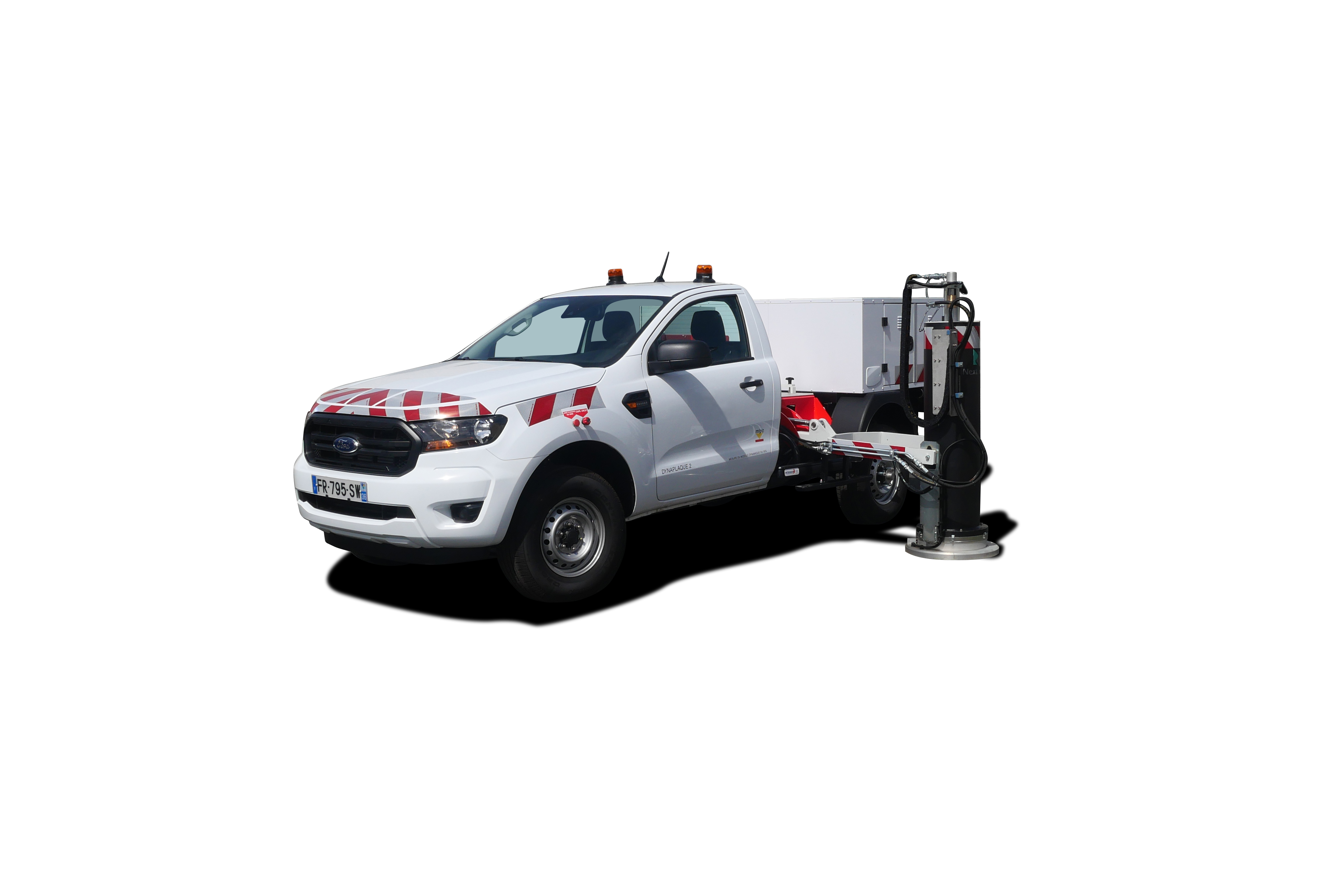
The system is mounted in a fixed position on the chassis of a light 4×4 vehicle or utility vehicle and allows many measurement points per day to be effortlessly performed compared to the traditional plate test.